Wednesday, November 28, 2012
Thursday, November 22, 2012
Hola Amiga
Hola Amiga
The work of Nate Williams, now available on pillows!
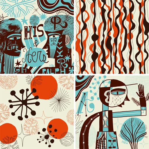
http://www.designworklife.com/2010/01/15/nate-williams-pillows/
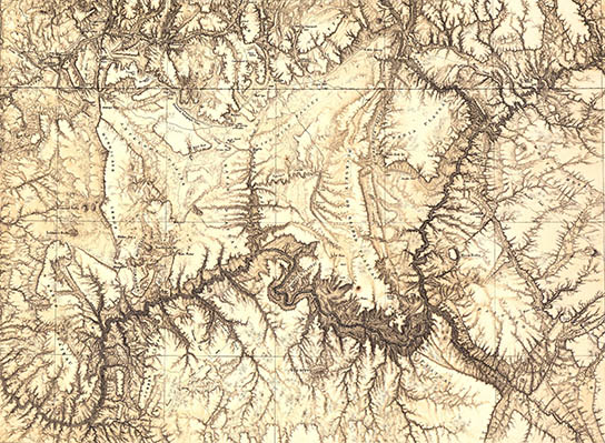
Topographic Map Rules
Topographic Map Rules

Contour maps provide an easy method of depicting the changes in elevation across an area. They let anyone visualize the shape of a landscape without having to fly overhead. Knowing a few simple rules can increase the amount of information gathered from any topographic map and help you interpret the features of any landscape.
Other People Are Reading


Contour Lines Never Cross
- Lines indicating elevation should never intersect on a topographic map, because each line represents a different elevation, so it is impossible to have two elevations at the same location.
Measuring Steepness
- The closer together contour lines are, the steeper the slope of the hill. If the spacing between lines stays the same then the slope is constant. If the distance between lines changes, then the slope also changes.
Stream Flow Direction
- When contour lines cross valleys, they will form a V shape. The V always points uphill. You can use this to determine which way water will flow across an area depicted on a topographic map.
Contours Close
- Contour lines form irregular circles and do not end at a random point. Every contour line can be followed around back to where it started, although this may be beyond your map's borders.
Concentric Circles
- Concentric circles represent hilltops and depressions. A depression or hollow where the elevation drops and is surrounded by higher terrain will be marked by closed irregular contours with hash marks on the line. The markings point inward from the edge and indicate that the area inside is lower. These areas will appear to have a crater or bowl shape.
Elevation Between Lines
- The elevation between two contour lines is never higher than the value of the higher contour line. For example, between a contour line marking 500 feet and another marking 600 feet, there could not be a point where the elevation is 650 feet without additional contour lines.
Read more: Topographic Map Rules | eHow.com http://www.ehow.com/list_6875833_topographic-map-rules.html#ixzz2CyUgGuUG
http://www.ehow.com/list_6875833_topographic-map-rules.html
Creating a Terrain with Contour Splines
First you will need the contour data for a given site; this can usually be obtained from GIS and converted to AutoCAD. In this example we are using contours from Laurel Hill Louisiana.
1. Open up 3ds Max and select file, import and navigate to your AutoCAD contour file and select open.
2. The following menu pops up. Generally you will not have to rescale the data, but the option is available as well as some others. The default settings will usually suffice, simply select OK.

3. At this point your contour linework will show up in the windows. You will need to select the lines and set their elevation via the Z Axis. Press h to open the selection window and select a contour, in this case the 210 ft elevation line.

4. Then simply choose the select and move tool and go down to the cartesian plan corrdinate entries, and type in 210 into the Z Axis. Press Enter.

5. Repeat this process for all contours and their respective elevations.
6. Once this is done, select all of the contours/objects and from the rollout on the right select the Create, thenGeometry buttons and choose Compound Objects from the rollout menu below.

7. Select Terrain from the options and a terrain is created from your contour splines!

8. You can also use the options under terrain to add color to the terrain, either manually or with the default settings.

3ds max provides a good preview of the terrain, but you should render it out to get an accurate view of it.

http://lab.visual-logic.com/2010/02/creating-a-terrain-with-contour-splines/

DODECAGON


http://www.nikolasschiller.com/blog/index.php/archives/category/renderings/quilt/dodecagon/
Monday, November 19, 2012
โอ๊ย โอ๊ย
มินิมัล แอนด์ เลส อิส มอร์ ไม่อาจบังเกิดในจินตนาการของฉันได้ ใครก็ได้ช่วยที หรือต้องไปบวชชี เกลาความฟุ้งซ่าน ให้เหลือแต่ฟังเชิ่นรึเปล่า? โถ่!! I can only Look not SEE "Minimalism" or "Less is More". So how can I get it how howwww howwwwwwwwwwwwww
Naoto Fukasawa from Moleskine
Website: http://www.naotofukasawa.com/
http://www.moleskine.com/authors-detail?groupId=10180&articleId=41457#.UKqQ6uRg8a4

Sunday, November 18, 2012
Lamp - A N I M A L studio


The idea of the pattern is based on simple semi-regular pentagonal tiling which was applied to a double sided lamp shade form in order to create a delicate, lace like effect.
Lamp ∅ 7"/ 18 cm, height 6"/ 15 cm
Colors: White
Stereolithography Printing
Colors: White
Stereolithography Printing
UL listed
Bulb: E12, 40W.
185 " long cord with a plug connector. Hard wiring capable.
2 ceiling hooks are included.
Bulb: E12, 40W.
185 " long cord with a plug connector. Hard wiring capable.
2 ceiling hooks are included.
http://www.aminimalstudio.com/
Laser-How to?
Basics: What the laser can do:
The laser can cut or etch. The materials that the laser can cut include wood, paper, cork, plastic etc. Etching can be done on almost anything, wood, cardboard, aluminum, stainless steel, plastic, marble, stone, tile, and glass.
A few “restricted materials” for the laser are PVC, vinyl and Lexan. These products contain chlorine, which when burnt by the laser, creates a gas that destroys the laser’s mechanism. Metal can be etched but this type of laser does not cut metal.
Inside the laser cutter’s chassis there is a powerful invisible infrared laser that is bounced off of a few mirrors and is finally directed towards the material being cut or etched by a moving mirror and lens that aims the focused beam.
There are two main variables that the laser uses to cut and etch, they are speed and power. When cutting, the laser power is increased and the speed is decreased so that the cutting beam spends a longer time hitting the material in order to cut though. While etching the speed is increased and the power reduced, this way the laser only removes a little material from the surface, leaving just the etching.
A 1/2” square hole drawn in an illustration software.
Drawing preparation:
The laser cutter / etcher driver software works with postscript files.
Vector Cuts:
Drawings with vector artwork are used to tell the laser to produce a cut and are called ‘vector cuts’. Lines that are "hairline" or smaller than .007" will be cut by the laser. When etching be careful of objects like gradient filled boxes with thin border, because the box’s thin boarder could be cut out. For best results make lines that you would like cut .001" and all others to larger then 0.009".
A minimum spacing of 1/32” between pieces is recommended so that the heat from the second cut does not reattach the cut line from the first cut. Also the thinnest piece should be a minimum of 1/8”. Pieces thinner than this will result in pieces that are too fragile, and possibly warped pieces.
Building Joints:
There are two aspects of the laser beam that must be taken into account when making parts that must fit together closely.
- 1.The kerf of the beam
- 2.The angle of the beam created by the focus.
Beam kerf:
The beam that the laser fires though the material being cut is thin, but it does still have a Kerf. Kerf is the width of the hole that the beam leaves after it has made a cut.
If you make a hole that is exactly 1/2” (0.500”) square in your drawing program, the hole that you will end up with will be around 0.506”. Holes are around 0.006” bigger than drawn.
This is how the laser cuts same 1/2” square hole, note that the hole is actually 0.506”
The same goes for cutting out solids. If you are trying to make rectangle that is exactly 1/2” (0.500”) wide, the laser will cut a rectangle that is about 0.490” wide.
Points to note:
- 1.Holes are cut about ~ 0.006” wider than drawn.
- 2.Solids are cut out about ~ 0.010” thinner than drawn.
A 1” x 1/2” rectangle drawn in an illustration software
The laser cuts solids about 0.010” thinner than drawn. Here the 1/2” side of the rectangle is 0.492”
These are small tolerances, and for many projects do not matter. But, if you are building something that uses mechanical connections like slots or finger groves to fit together, it can make the between two pieces fitting together nicely, and holding with friction verses two pieces that need a lot of glue to stay together.
If you are just starting with the laser, it’s best to cut pieces the same size, or only adjusted slightly. If two pieces are forced together too tightly, there is a risk that the parts will crack. This is especially true with acrylic.
Beam angle:
After the laser beam leaves the CO2 laser tube it is wide and unfocused, but it does travel in a straight line. In most laser cutters the beam gets bounced off of a few mirrors positioned at 45° angles until the beam is heading down toward the material that you want to cut or etch.
At this point it travels though a focusing lens. This lens makes the wide beam into a small point. This focal point is used to vector cut, or raster etch.


If the laser is etching, the focal point is adjusted to be directly on the surface. But if the laser is being used to cut, focusing on the surface may not be the best choice.
Here are some very exaggerated angles that can be cut into the material, depending on where the focal point is set.
Illustration of laser focal point.

Exaggerated example of the angle that can be produced through materials being cut by varied focal points.


The thicker the material being cut, the more this angle will be noticeable. Most often this angle is not noticeable, and only in the range of around 0.004” on a material 1/4” thick that was top focused.


Working with Acrylic:
Cleaning:
Dust and fingerprints:
The best way to clean dust and finger prints is to use a product like Windex™ with either a good quality paper towel or a lint free rag. You can also use soap and water.
Greases and Glues:
Through lots of experimenting, the best way that to remove the glue from masking tapes is to use WD-40™. WD-40™ will dissolve most glues when used with a rag or paper towel. WD-40™ smells strongly and can leave the acrylic with an oily feeling. A follow-up with Windex™ is usually needed to get that “squeaky” clean feeling.
Gluing:
Glue:
Acrylic is actually welded with glue rather than being surface glued. Acrylic glue is watery thin and available at a plastic supplier or hobby shop. Make sure you get glue that works with acrylic and not just other plastic. In a pinch you can use cyanoacrylate glue i.e. Crazy glue. If the gap between parts is large, small bits of acrylic may be dissolved into acrylic glue to make a gap filling cement.
Be careful with the acrylic glue, and try not to get it on your skin, it is toxic.
Technique:
The working time with acrylic glue is very short, around 5 seconds. The best way to glue two pieces together is to hold them in position and place a small drop on the surface between them. The glue will wick into the joint, pulled by surface tension. When gluing clear plastic you can see the glue flow. Be careful not to get any glue where you don’t want it, it will ruin the look of the surface.
If your parts are small and flat you can put a drop on one part and them squeeze them together until they hold, around 10 seconds.

Raster Etch:
The laser is capable of using shades of grey for raster etching. The darker the area the more power the laser uses. This allows it to reproduce photographs or artwork with incredible detail. The results vary with the type of material that you are etching onto. For example, the darker area in artwork etched onto wood will be darker and deeper, but the same photo etched onto aluminum the dark area of the artwork would come lighter! The reason for this is that the more you "burn" wood the darker it gets but the more you etch aluminum the lighter it gets.
Vector Etch:
Vector etching, is similar to vector cutting except the speed that the laser is increased to the point were laser does not stay on any one point long enough to cut all the way through the material. The result is a very thin line cut into but not though the material.


A vector cut
Raster etch. Here the etched plastic was filled with red acrylic paint for more contrast. Note: a vector cut was used around each number to free it from the board. These cut out numbers are attached to buttons on a panel.
Vector etch
These products work well to clean acrylic safely.
Glueing acrylic
http://spikenzielabs.com/SpikenzieLabs/Laser_How_To.html


Things not to use:
Acrylic really doesn’t like products with alcohol in them. On colored acrylic it is not as noticeable. On clear acrylic, you will see very small, but noticeable cracks along the cuts and etched areas. (It looks a like a car windshield that has been hit by a rock.)
Products not to use, include nail polish remover, electronics contact cleaner, isopropyl alcohol, or solvents containing alcohol as one of their ingredients.
Subscribe to:
Posts (Atom)